Wiring
This page describes how the Arduino Nano on the control board connects to everything else.
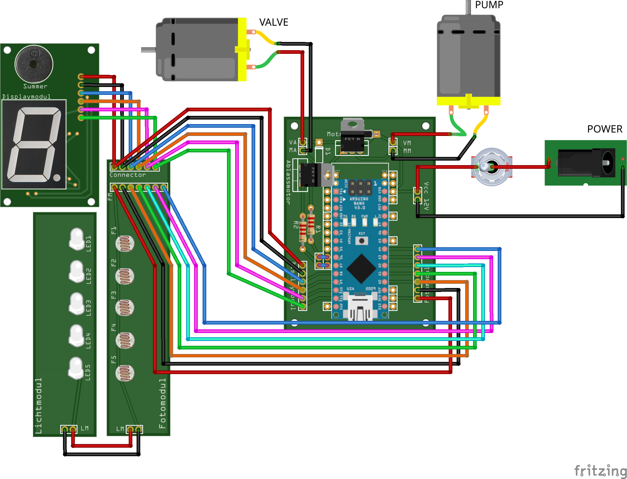
Master pin map
| Function | MCU pin | Dir | Connects to |
|---|---|---|---|
| Card reader bit 0 | A0 | in | Fotomodul 7-pin (pin 3) |
| Card reader bit 1 | A1 | in | Fotomodul 7-pin (pin 4) |
| Card reader bit 2 | A2 | in | Fotomodul 7-pin (pin 5) |
| Card reader bit 3 | A3 | in | Fotomodul 7-pin (pin 6) |
| Card reader bit 4 | A4 | in | Fotomodul 7-pin (pin 7) |
| Pump (inflate) | D6 | out | Steuermodul MA/MM → TIP120 → AIRPO pump |
| Valve (deflate) | D7 | out | Steuermodul VA/VM → TIP120 → CEME solenoid |
| Display data (DS) | D8 | out | Displaymodul pin 3 → 74HC595 serial data |
| Display latch (STCP) | D9 | out | Displaymodul pin 4 → 74HC595 storage clock |
| Display clock (SHCP) | D10 | out | Displaymodul pin 5 → 74HC595 shift clock |
| Buzzer | D11 | out | Displaymodul pin 6 → piezo buzzer |
| RNG seed | A5 | — | must stay unconnected (floating) |
Leave A5 floating
A5 is deliberately not connected. The firmware reads its floating,
noisy analog value to seed the random-number generator. Wiring it to
anything would make the seed deterministic and hurt game randomness.
Power
A single 12 V / 3 A supply powers the whole device, entering through a switched DC socket:
- 12 V rail → the pump and the valve (switched by the two TIP120 channels on the control board).
- 5 V logic rail → derived on the Arduino; powers the Arduino itself and the display module (74HC595 + buzzer).
- 3.3 V → the card reader's Fotomodul, for a
stable analog reference on
A0–A4.
Where the connectors live
All three modules meet on the control board:
- Fotomodul 7-pin — 3.3 V, GND, and
A0–A4(see the card reader). - Displaymodul 6-pin — 5 V, GND,
DS/STCP/SHCP, and buzzer (see the display). - 12 V input and the pump/valve output terminals (
MA/MM,VA/VM).