Display
The display (Displaymodul) is the device's only visual output: a single 20 mm 7-segment digit that shows the current player number, countdowns, and game state. It also carries the piezo buzzer for game sounds. Both are driven from just four Arduino pins, because the segments go through a shift register.
Circuit
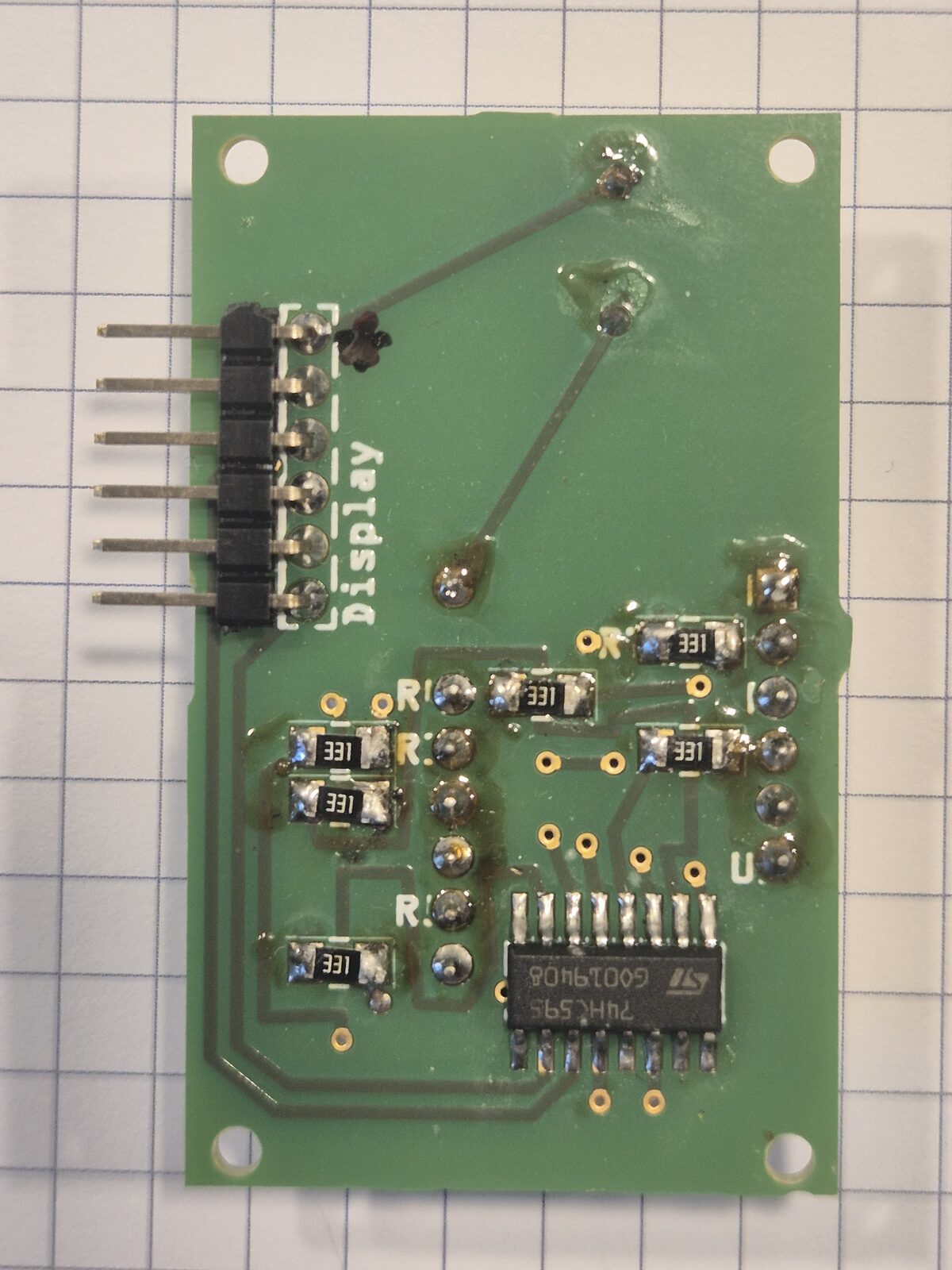
A single 74HC595 shift register (SMD) drives the display. The Arduino clocks 8 bits into the register serially; the register's eight outputs drive the seven segments plus the decimal point, each through its own 330 Ω current-limiting resistor (8× 330 Ω total). This trades three fast MCU pins for eight segment lines.
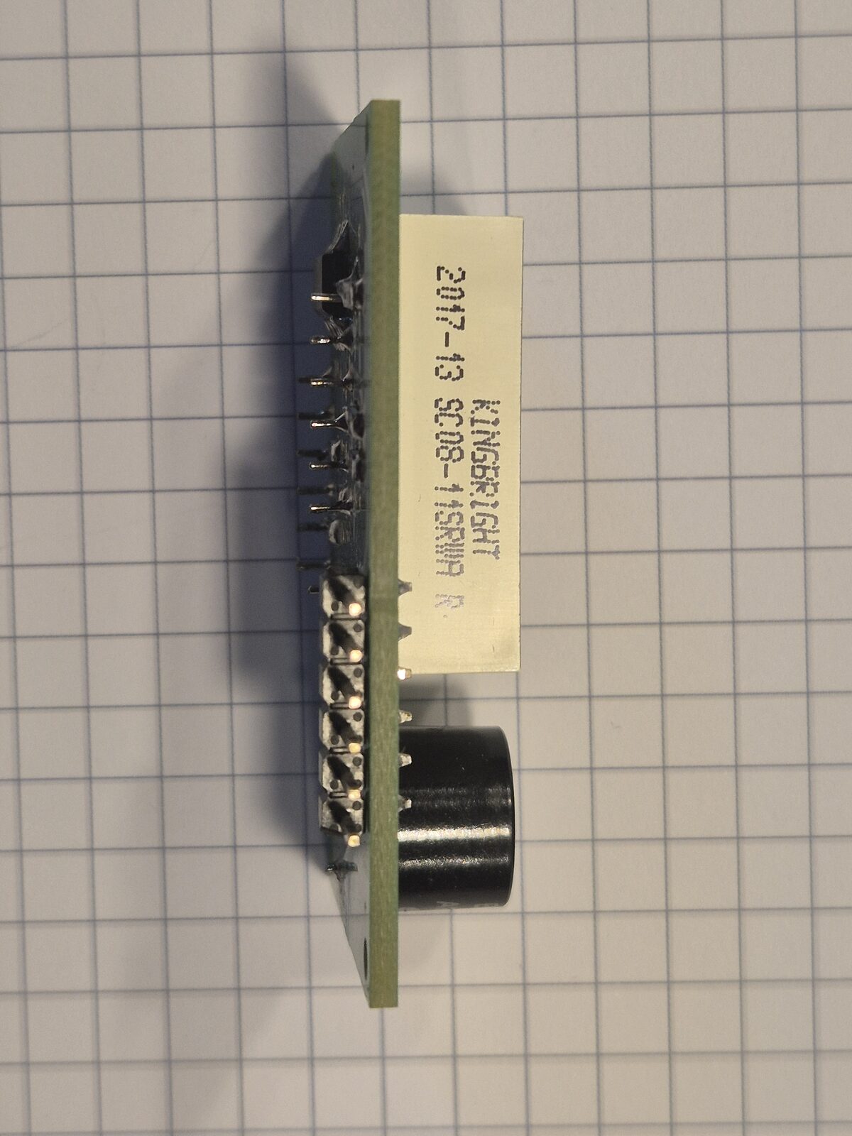
The 7-segment digit is common cathode (part SC08-11). The buzzer (EKULIT AL-60P12) is driven directly from a dedicated MCU pin.
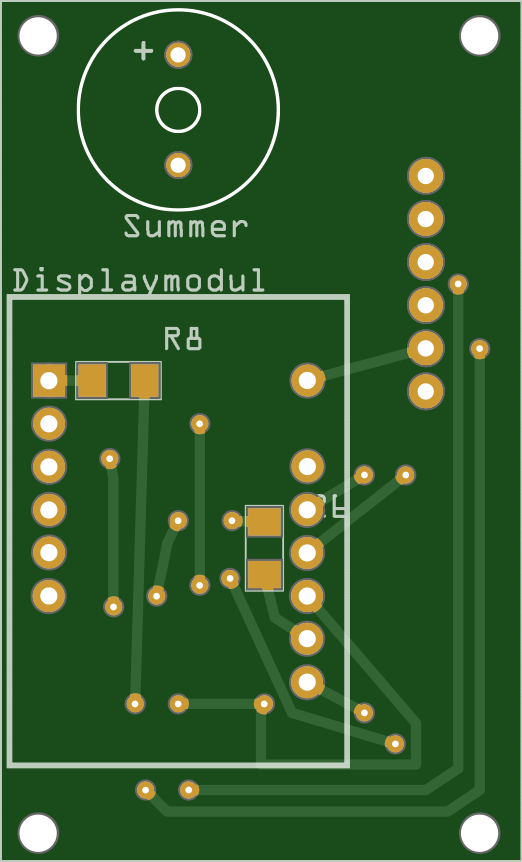
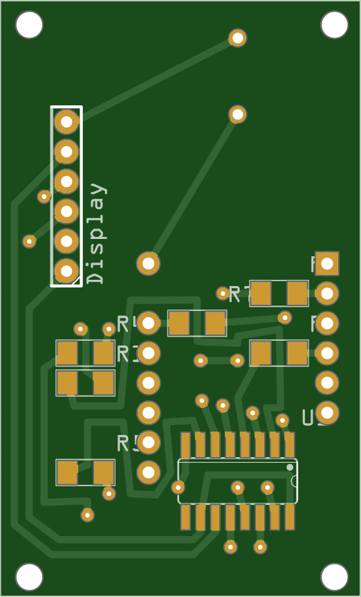
Board markings
| Marking | What it is |
|---|---|
Summer |
The piezo buzzer (Summer is German for buzzer). The + marks its positive pin. |
U1 |
The 74HC595 shift register, an SOIC-16 SMD part on the bottom side. The dot and the notch in its outline mark pin 1. |
R1–R8 |
The eight 330 Ω series resistors, one per shift-register output: seven segments plus the decimal point. SMD, bottom side. |
Display |
The 6-pin connector to the control board. Pinout in the table below. |
Parts & datasheets
The components populated on the board, with the datasheet for each part archived in the repo where available. The eight segment resistors are the same 330 Ω SMD 1206 part used elsewhere — see the note on the BOM page.
| Component | Qty | Part / supplier | Datasheet |
|---|---|---|---|
| 7-segment 20 mm digit (common cathode) | 1 | SC08-11 | |
| 74HC595 shift register (SOIC-16, SMD) | 1 | SMD HC 595 | |
| 330 Ω resistor (SMD 1206) | 8 | Reichelt SMD 1206, segment resistors | |
| Piezo buzzer | 1 | EKULIT AL-60P12 |
Gallery
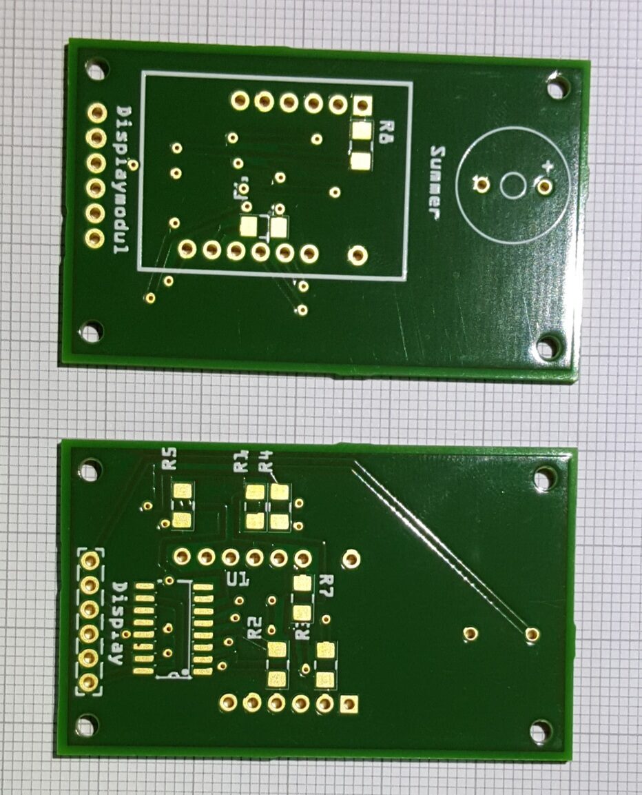
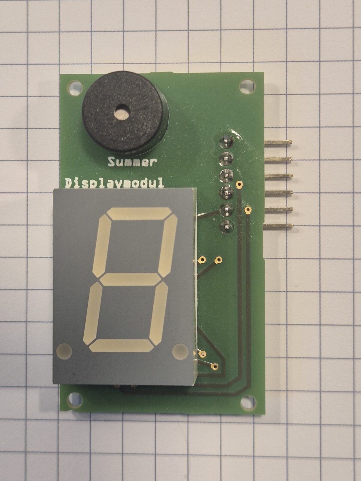
Photos of the board, before and after assembly. Click any of them for a larger view.

Fritzing source:
Displaymodul.fzz.
Connector (6-pin)
The module connects to the control board through a 6-pin header. The three shift-register control lines and the buzzer map to Arduino digital pins as shown. The module runs at 5 V:
| Pin | Signal | 74HC595 role | MCU pin |
|---|---|---|---|
| 1 | Vcc | +5 V | — |
| 2 | GND | — | |
| 3 | DS | serial data in | D8 |
| 4 | STCP | storage-register clock (latch) | D9 |
| 5 | SHCP | shift-register clock | D10 |
| 6 | Buzzer | piezo buzzer drive | D11 |
To update the digit, the firmware shifts 8 bits out on DS/SHCP (D8/D10),
then pulses STCP (D9) to latch them to the outputs. For the complete signal
map across all modules, see the wiring.