Card Reader
The card reader (Kartenmodul, card module) is how the device knows which card a player has inserted. It is an optical reader: it shines light through the card and measures where the light gets through.
It is built from two stacked PCBs:
- the Lichtmodul (light module) — the illuminator, and
- the Fotomodul (photo module) — the sensor.
A card slides into the gap between them. Each card carries a pattern of clear and opaque spots; the sensors below read that pattern as a 5-bit value. The encoding itself is documented separately in the Optical Code System reference.
Lichtmodul (light module)
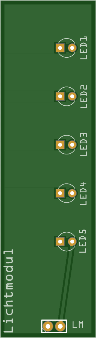
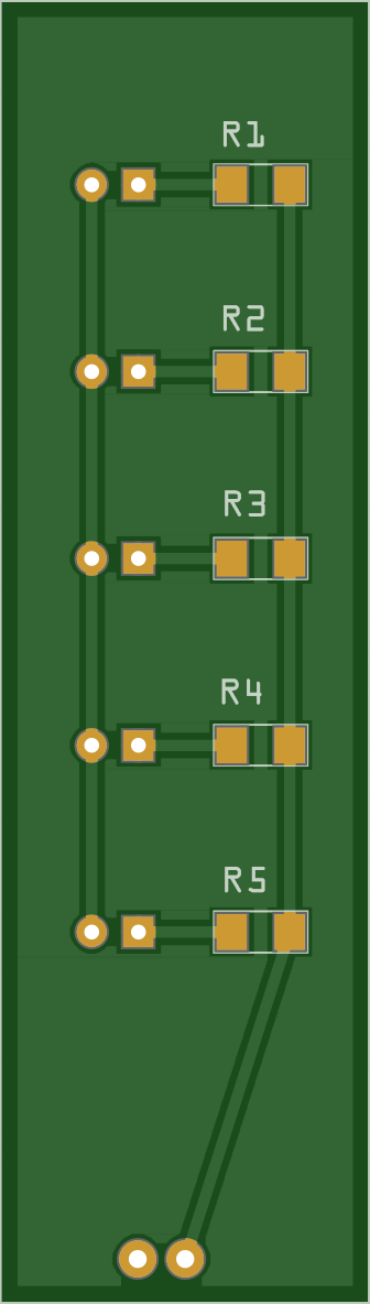
The Lichtmodul is the light source. It carries 5× 3 mm LEDs, each with its own 330 Ω series resistor to limit current. The five LEDs sit directly above the five sensors on the Fotomodul, so each sensor is lit from above through the card.
Board markings
| Marking | What it is |
|---|---|
LED1–LED5 |
The five 3 mm LEDs. |
R1–R5 |
The 330 Ω series resistor belonging to the LED of the same number, mounted as SMD parts on the bottom side. |
LM |
The 2-pin connector (Lichtmodul) carrying power for the LEDs. It plugs into the matching LM header on the Fotomodul below. |
1 |
Pin-1 marker, printed next to LM. |
Parts & datasheets
The components populated on the Lichtmodul, with the datasheet for each part archived in the repo where available.
| Component | Qty | Part / supplier | Datasheet |
|---|---|---|---|
| 3 mm white LED | 5 | Reichelt LED EL 3-11250KW (Bürklin 67 S 4470) | |
| 330 Ω resistor (SMD 1206) | 5 | Reichelt SMD 1206, LED series resistor |
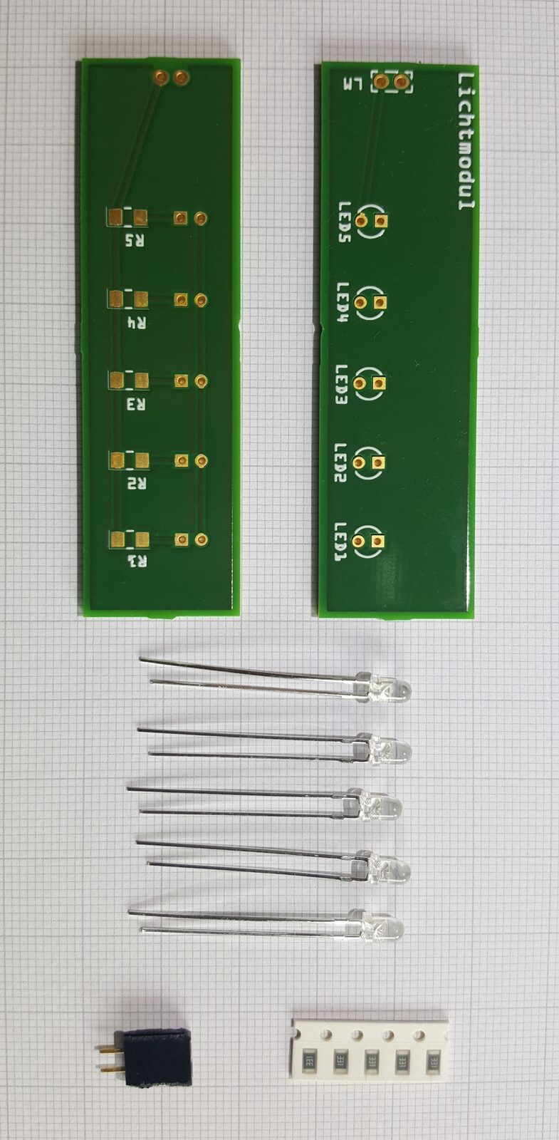
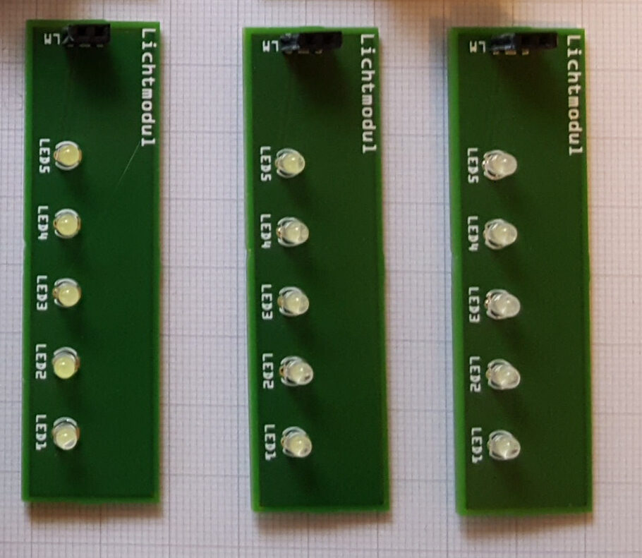
Gallery
Photos of the board, before and after assembly. Click any of them for a larger view.
Fritzing source:
Kartenleser_Lichtmodul.fzz.
Fotomodul (photo module)
The Fotomodul is the sensor board. It carries 5× photoresistors
(light-dependent resistors, Reichelt A 905014), each forming a
voltage divider with a 330 Ω resistor. Each divider's midpoint feeds one
of the Arduino's analog inputs, A0–A4. A lit sensor (light passing through a
clear spot on the card) and an unlit sensor (light blocked by an opaque spot)
produce clearly different analog voltages, which the firmware thresholds into
the 5 bits of the card code.
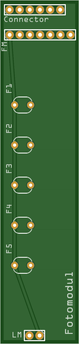
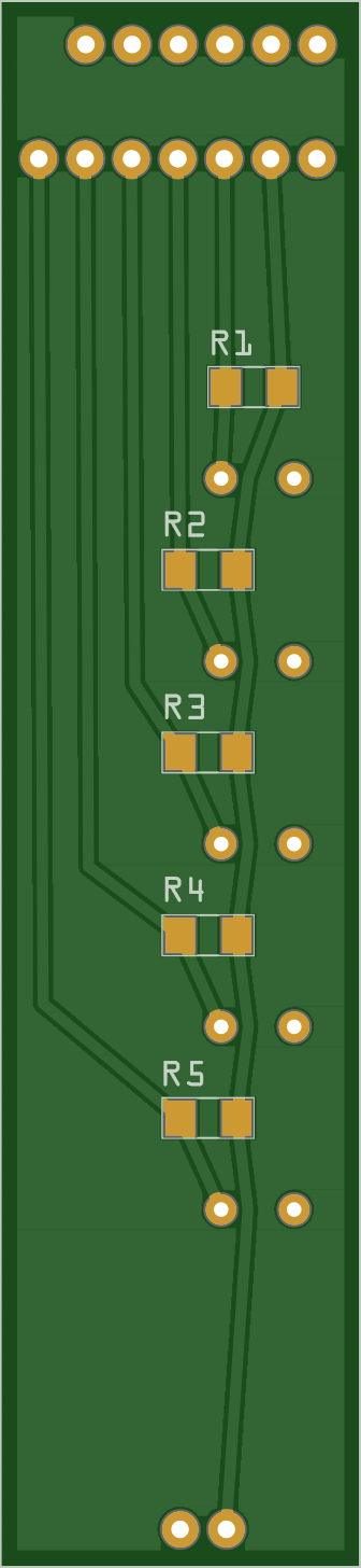
Board markings
| Marking | What it is |
|---|---|
F1–F5 |
The five photoresistors. Each one lines up under an LED on the Lichtmodul. |
R1–R5 |
The 330 Ω divider resistor belonging to the sensor of the same number, mounted as SMD parts on the bottom side. |
LM |
The 2-pin header that feeds the Lichtmodul stacked above. |
FM |
The 7-pin header to the control board — 3.3 V, GND, and A0–A4. Pinout in the table below. |
Connector |
A 6-pin pass-through for the display cable, electrically no part of the card reader. The control board sits at the bottom of the case and the Fotomodul in the middle, so relaying the display cable through here keeps the display in the lid easy to unplug. |
1 |
Pin-1 marker, printed next to LM and FM. |
Parts & datasheets
The components populated on the Fotomodul, with the datasheet for each part archived in the repo where available. Its 330 Ω divider resistors are the same SMD 1206 part as on the Lichtmodul — see the note on the BOM page.
| Component | Qty | Part / supplier | Datasheet |
|---|---|---|---|
| Photoresistor (LDR) | 5 | Reichelt A 905014 (Conrad 145475-62) | |
| 330 Ω resistor (SMD 1206) | 5 | Reichelt SMD 1206, divider resistor |
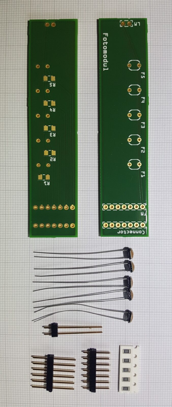
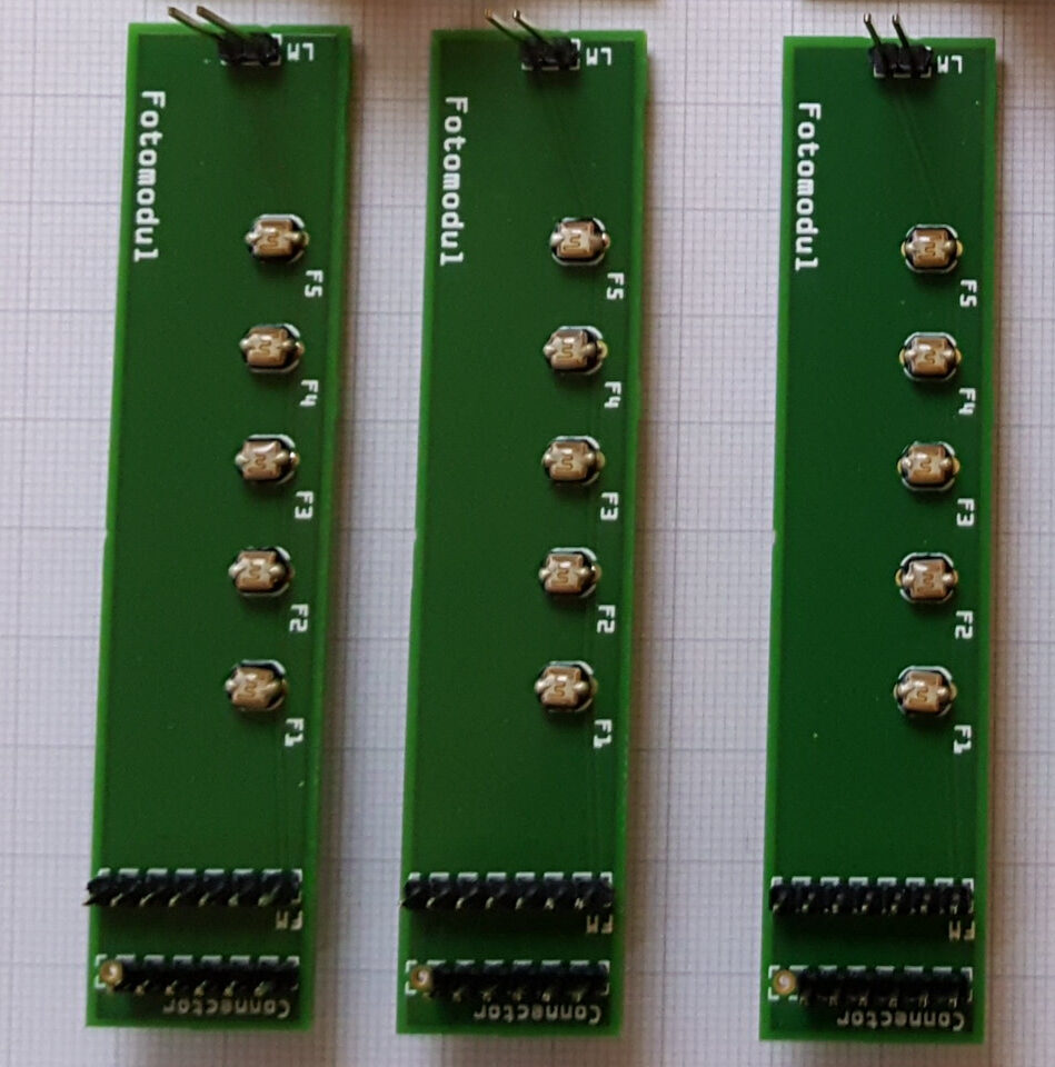
Gallery
Photos of the board, before and after assembly. Click any of them for a larger view.
Fritzing source:
Kartenleser_Fotomodul.fzz.
Fotomodul connector (7-pin)
The Fotomodul connects to the control board through a 7-pin header. Note the module runs at 3.3 V, not 5 V, for a stable analog reference:
| Pin | Signal | Notes |
|---|---|---|
| 1 | Vcc | 3.3 V |
| 2 | GND | |
| 3 | A0 | card bit 0 |
| 4 | A1 | card bit 1 |
| 5 | A2 | card bit 2 |
| 6 | A3 | card bit 3 |
| 7 | A4 | card bit 4 |
The A0–A4 lines land on the Arduino's analog inputs. For the complete signal
map across all modules, see the wiring.
Calibration
Because photocell behaviour depends on the exact LEDs, ambient light, and card
material, the firmware ships with a bring-up harness that prints raw analog
values so you can pick thresholds. See
DETECTOR_CALIBRATION on the
firmware page.