Control Board
The control board (Steuermodul, control module) is the hub of the device. The Arduino Nano sits on it, the 12 V power comes in here, and the other two modules — the card reader and the display — plug into it. It also carries the power electronics that switch the two 12 V loads: the inflate pump and the deflate valve.
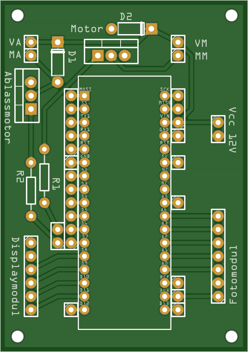
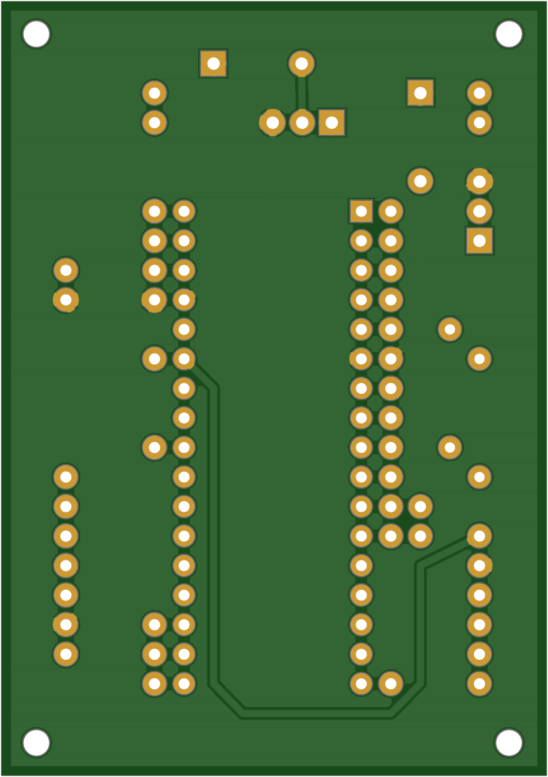
Board markings
| Marking | What it is |
|---|---|
Motor |
The 3-pin footprint for the pump channel's TIP120 (Motor = the inflate pump). |
Ablassmotor |
The same for the valve channel (Ablassmotor = release motor, the deflate solenoid). |
D1, D2 |
The 1N4004 flyback diodes, one per channel, cathode toward +12 V. |
R1, R2 |
The 2.2 kΩ base resistors, one per channel, between the MCU pin and the transistor base. |
MA, MM |
The pump output terminals, 12 V switched by D6. |
VA, VM |
The valve output terminals, 12 V switched by D7. |
Vcc 12V |
The 2-pin 12 V supply input. |
Fotomodul |
The 7-pin header to the card reader. |
Displaymodul |
The 6-pin header to the display. |
1 |
Pin-1 marker, printed next to each keyed header. |
The single unlabelled pads in rows beside the Arduino footprint are direct break-outs of its pins, there so a signal can be tapped or jumpered by hand.
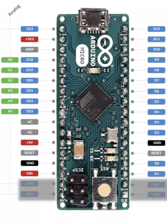
Fitting the Nano in the Micro footprint
The footprint has 17 holes per row — the Micro's pin count. The Nano has
15 per row, but the two layouts are compatible by design: the Micro's pinout
is the Nano's plus two extra pins per row at the far-from-USB end (its SPI
pins D14–D17), and its NC positions sit where the Nano has A6/A7.
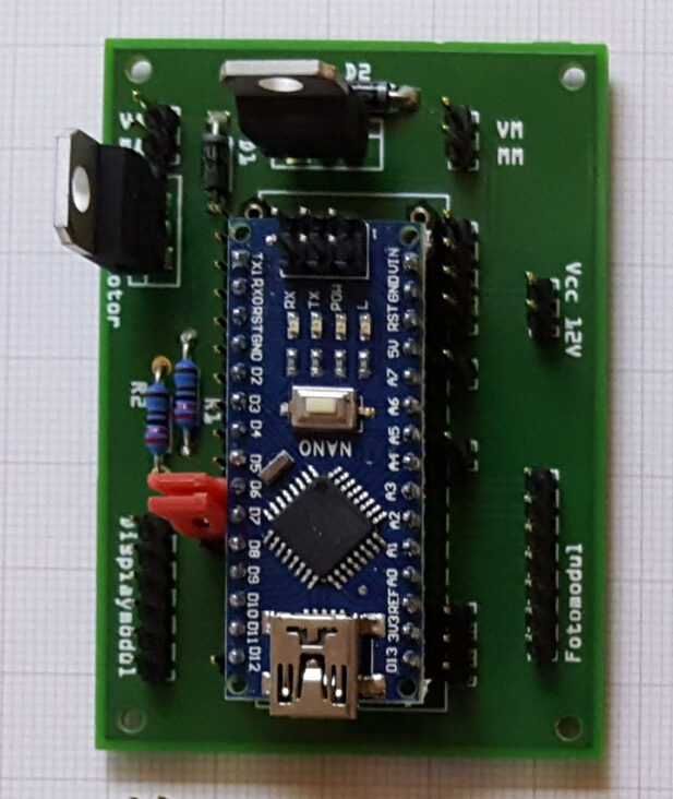
Compare the two boards (both shown from the top, USB up):
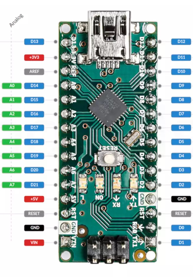
To place the Nano on the board:
- USB connector toward the
Displaymodul/Fotomodulheaders — the same direction the Micro's USB would face. TheD12andD13holes are in that corner of the footprint. - Align flush with that USB end. Every Nano pin then sits in the hole
carrying its own name:
TX1→TX1…D12→D12on one row,VIN→VIN…D13→D13on the other.
Parts & datasheets
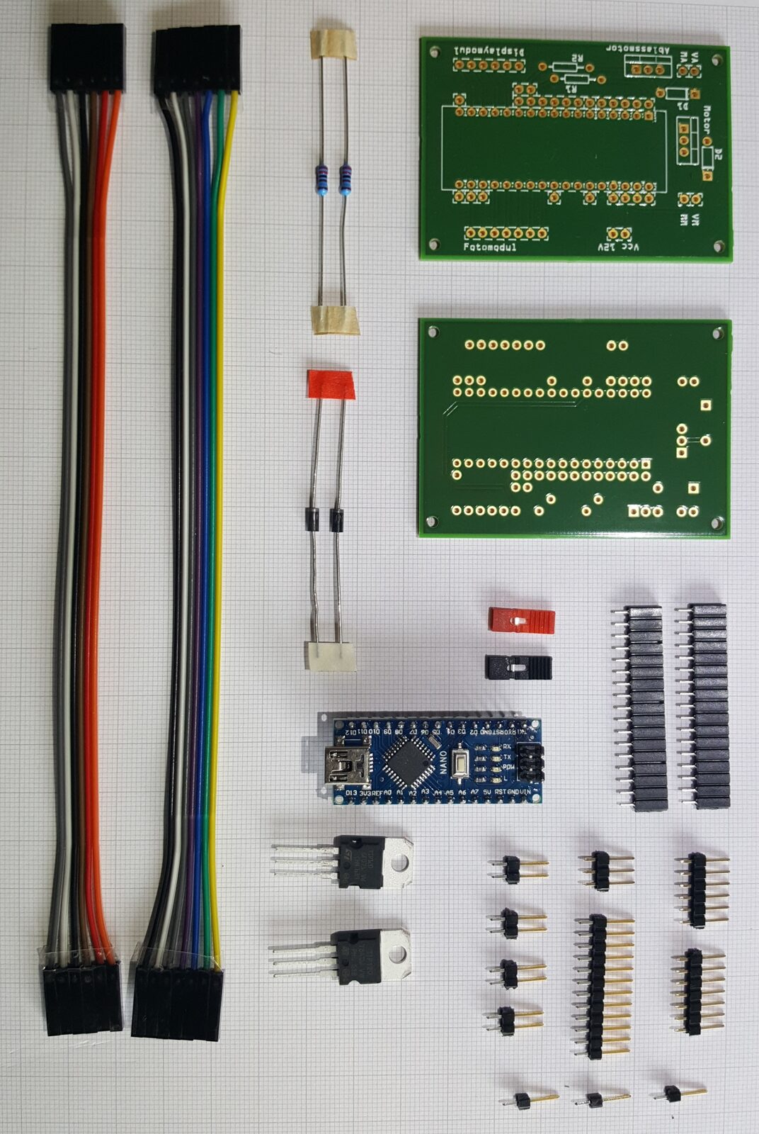
The components populated on the board, with the datasheet for each part archived in the repo where available.
| Component | Qty | Part / supplier | Datasheet |
|---|---|---|---|
| Arduino Nano (ATmega328P) | 1 | Keywish Nano (footprint drawn for an Arduino Micro) | — |
| TIP120 Darlington transistor | 2 | STM (Reichelt) | |
| 1N4004 flyback diode | 2 | Fairchild | |
| 2.2 kΩ resistor (metal film) | 2 | Reichelt METALL 2,20K, transistor base |
The board is also the wiring hub for the power-entry parts and the two 12 V loads it switches. These are not on the PCB — they mount in the enclosure and land on the screw terminals — but are listed here since they are electrically part of this module:
| Component | Qty | Part / supplier | Datasheet |
|---|---|---|---|
| DC socket (switched) | 1 | BKL 072342 | |
| Toggle switch (on/off) | 1 | MS-165 series | |
| Membrane pump (inflate) | 1 | AIRPO D2028B (12 V) | |
| Solenoid valve (deflate) | 1 | CEME 5000EN1,5P |
Gallery
Photos of the board, before and after assembly. Click any of them for a larger view.
12V Power switching
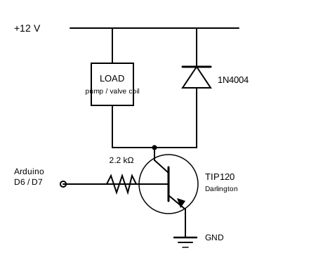
The Arduino cannot drive the 12 V pump or valve directly, so each load has a TIP120 Darlington transistor acting as a low-side switch. There are two identical channels:
- Pump channel — output terminals MA/MM (Motor), drives the AIRPO D2028B membrane pump (inflate). Controlled by MCU pin D6.
- Valve channel — output terminals VA/VM (Ventil, valve), drives the CEME 5000EN1,5P solenoid valve (deflate). Controlled by MCU pin D7.
Each channel is the textbook TIP120 low-side driver: the MCU pin drives the
base through a 2.2 kΩ resistor, the load sits between +12 V and the
collector, the emitter goes to ground, and a flyback diode bridges the load
(cathode to +12 V) to clamp the inductive kick when the transistor switches
off. One channel looks like this (Dx is D6 for the pump, D7 for the
valve):
The design basis is the TIP120 tutorial, archived here as
Motorsteuerung.pdf.
Connectors
Everything meets on this board:
| Connector | To module | Pins |
|---|---|---|
| Fotomodul header | Card reader | 7-pin (3.3 V, A0–A4) |
| Displaymodul header | Display | 6-pin (5 V, DS/STCP/SHCP/buzzer) |
| Power input | 12 V / 3 A supply | via switched DC socket |
| Pump output (MA/MM) | AIRPO pump | 12 V, switched by D6 |
| Valve output (VA/VM) | CEME valve | 12 V, switched by D7 |
Fritzing source:
Steuermodul.fzz.
For the complete, authoritative signal map — including which analog and digital pins each connector carries — see the wiring.